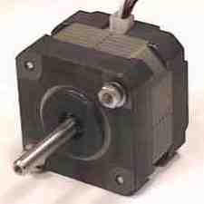
| KP4M4-001 Stepper Motor |
Some definitions
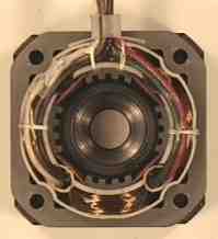
The rotating shaft with permanent
magnet attached is called the rotor. The stationary housing containing
the coil-wound poles is called the stator. With a unipolar motor,
the current only flows in one direction in the windings of the coils. i.e. the
stator poles can only be polarised one way.
In the KP4M4-001 stepper motor, the permanent magnet lies North - South along the shaft. It is encased in two "stacks" each with 25 teeth round the rim. The teeth on the South stack are out of phase with the teeth on the North stack by half the gap between teeth.
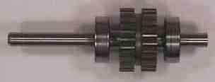
This means that at the same time that the teeth on the North stack are being attracted by and thus lining up with the teeth on the currently magnetised pole of the stator, the teeth on the South stack are being repelled and thus lining up with the gaps between the teeth on that pole.
With 25 teeth round the edge of the rotor and 4 coils excited individually in turn, the KP4M4-001 stepper motor takes 100 steps per complete revolution. The spacing between the teeth is 360° / 25 = 14.4°. When the teeth on the rotor are aligned with the teeth on the stator pole of the currently excited coil, they are misaligned by a quarter of that angle with the teeth on the next stator pole. So when the coil on that pole becomes energised instead, the rotor is pulled round through one quarter of 14.4° producing a step of 3.6°.
Flattening it all out makes it easier to illustrate (that's explain and draw) -
Generally, for this kind of stepper motor
| Steps per complete revolution | = | Number of phases (coils) x Number of teeth on rotor |
(With many other kinds of stepper motor, the number of coils does not equal the number of phases)
|
last updated: 27-Aug-96 Ian Harries <mailto:%20ih@doc.ic.ac.uk>